Team:NTHU Taiwan/SensingSystem
Overview
After fertilizing the crops, we also want to detect real-time soil data in the farm. However, the cost of setting up multiple sensors to cover the whole farm can be quite high and maintenance can be a huge pain. As a result, we built a linear motion Sensing System with a robotic arm to let us use only one sensor but get data from all over the farm.
Considering the feasibility and the purpose of demonstration, we built a much smaller prototype, meaning it would be mainly used for fine agriculture with higher economic values.
The Sensing System can be separated into six parts: Structure, ECU(Electricity Controller Unit) Box, Gateway Box, Robotics Arm, Linear Motion system and the Sensors.


Structure
In order to lower the cost, we applied the sheet metal from the robotics arm kit which we bought online. The sheet metal has been hardened by the surface treatment through sandblasting. However, we still designed and manufactured our own special parts to combine the robotics arm, the linear motion motor, and soil sensors.

ECU and Gateway Box
We put the IoT communication chips(LoRa shield), the power supplier, and the Arduino Mega along with the motor drive for our linear motion system inside the ECU Box, while the Gateway Box contains the Dragino Gateway. The reason we separated our device into the two parts mentioned above is to achieve modularization”. Not only for easy maintenance, but also durability.


Robotics Arm
The robotics arm is equipped with 4 MG996R stepper motors. Owing to the convenience of the inner gearbox and circuit of the servo motor, we can easily control the position of the arm precisely through the PWM signal.


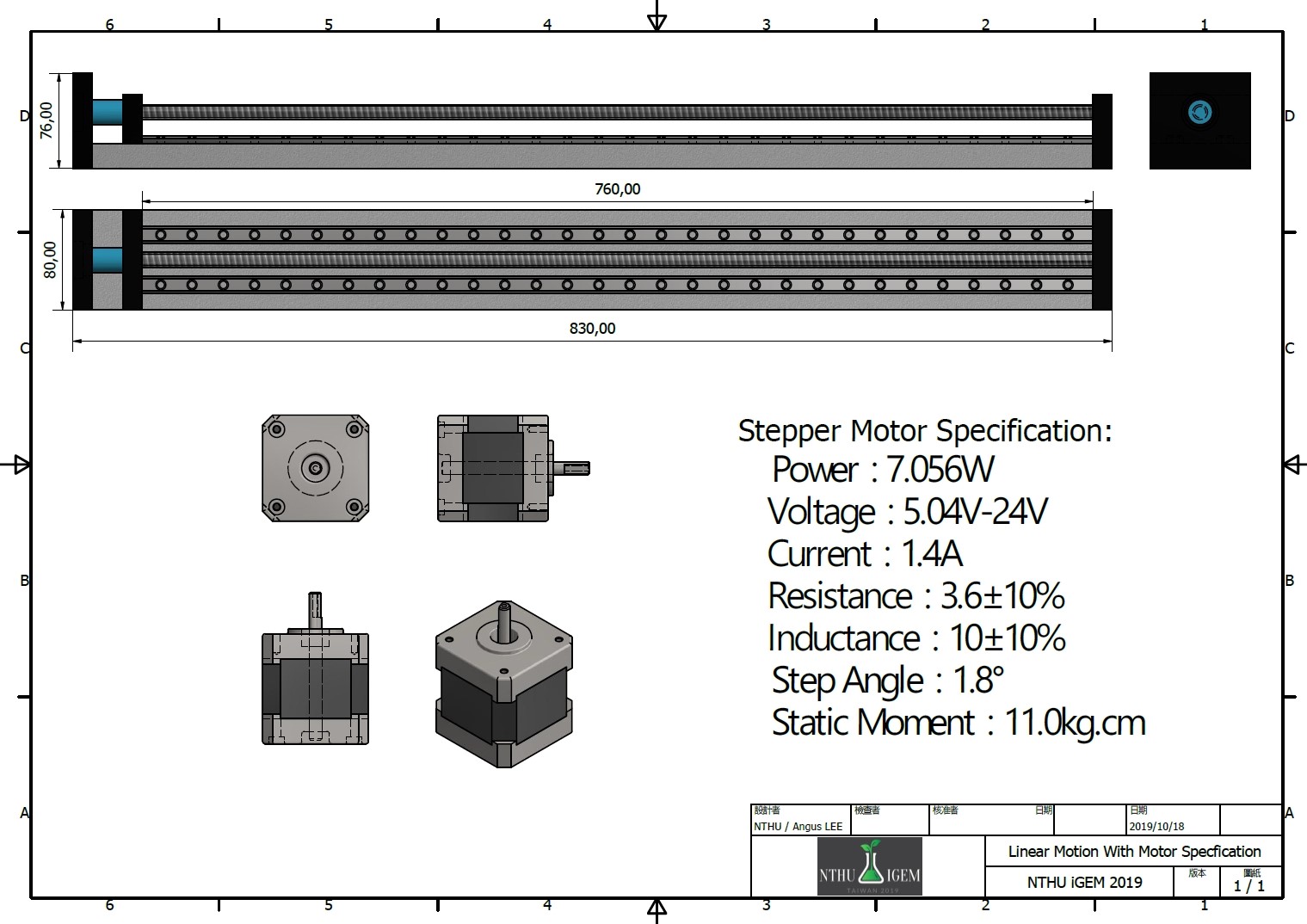
Linear Motion
To acquire data from various locations, we attached a ball screw to the linear motion stepper motor. As a result, we can control the arm equipped with the sensor to any Cartesian coordinate we assigned. Additionally, we used the A4988 driver chip to trigger the motor with the external power 12 Volt. supply.

Sensor
Because we want to detect the soil parameters promptly, we ordered the 3 in 1 sensor kit online(EC value and Temperature, Humidity). To turn the sensor voltage to a readable signal for the Arduino, we converted the standard industrial RS485 signal using an external module and deliver the converted signal to the Arduino for further processing.

FOLLOW US
CONTACT US
nthuxigem@gmail.com