

Hardware
One of the advantages of self-selecting directed evolution platforms is that they theoretically require less user intervention than screening-based systems. In order to fully exploit this benefit, we decided to create hardware to handle the processing steps required, with the eventual goal of fully automating our evolutions.
Specifically, we wanted to build hardware to address the interplay between the drift cassette and infection reporter described on our PREDCEL+ page. A schematic of the feedback control system envisioned is presented below:

Design
We wished to make a hardware module compatible with an Opentrons robot, which could provide constant mixing of the cells, add inducers as needed, and transfer phage between rounds of evolution. Our module needed to accomplish three things:
- Temperature control
- Light generation
- Fluorescence detection
To make our work broadly accessible to the iGEM community, we hoped to do this as cheaply as possible. We controlled our module using an ELEGOO UNO R3 board and programmed it using Arduino software.
Temperature Control
To maintain a constant temperature of 37 degrees throughout the experiment, we used a combination of a peltier and temperature sensor, models of which are given in the table below:

We also used the wiring shown in the schematic below:

Light Generation
To detect GFP fluorescence, we needed to provide a constant power source to emit light that corresponds to GFP’s excitation peak, though, for our two setups (described in a later section), we needed two different power requirements for our LEDs.
For our smaller volume, we could get away with using a smaller LED (water clear LED, peak wavelength 468 nm, forward voltage 12 V) that was bought on eBay. This could be directly connected to the 12 V power source we used above.
For our larger volume, we used a slightly more involved setup shown in the figure below:


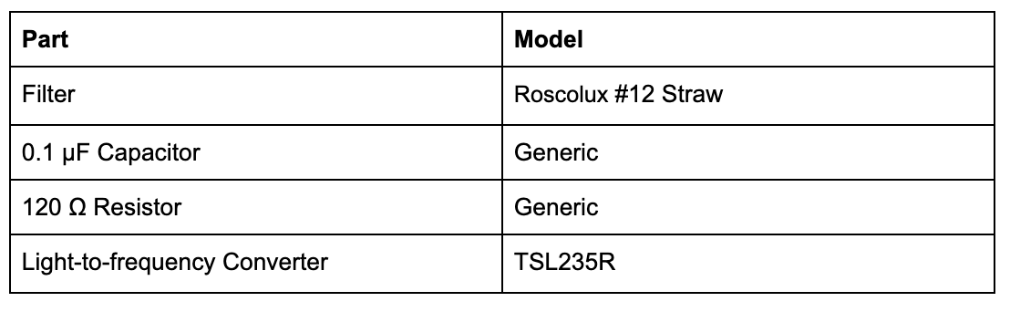
Fluorescence Detection
Inspired by the Aachen 2014 iGEM team, we used the TSL235R light-to-frequency converter to measure fluorescence over time. Unlike them, however, we used a different fluorescence filter (Roscolux #12 Straw - note, that is hard to get individual filters, so we ordered an entire set and picked from the set), which we glued in front of our light-to-frequency converter. See our setup below:

General Rack Setup
We went through multiple iterations of creating our OT1 rack. We first machined an aluminum block and glued a OT1 rack adaptor to the bottom as shown below. We then glued the appropriate excitation and emission filters onto the sides, as shown below:

However, one downside of this approach was that the rack needed to be washed and adequately sterilized after every use. We then switched to make our rack compatible with easily disposable plasticware to avoid this issue. We used two designs, one for 1 mL cuvettes and the other for 50 mL falcon tubes.
For our cuvette design, we 3D printed an enclosure for the cuvette on top of a platform to fit in the OT1 (the .stl files for both can be found on our github). We then covered the enclosure and platform with copper foil tape (Kraftex, 0683203920681) to allow attachment of the Peltier and temperature sensing units. Due to the small size of the unit, we attached our smaller LEDs to one end of the enclosure, and the light detection unit to the other end. See the picture below:

For our Falcon tube design, we machined an aluminum rod so that a 50 mL falcon tube could fit just inside. Two holes were drilled at the bottom to attach the larger LED setup and the light detection unit. The 3D printed platform was again used and covered with copper foil tape as above. We used thermal glue (Gennel, 0605826628065) to connect the machined rod to the platform. See the picture below for the full setup:

Results
As the video below shows, we were able to set up our first iteration of the rack with temperature control, constant mixing, and proper illumination. However, the illumination proved not to be intense enough given the large path length, so we endeavored to reduce the path length in future designs.
Our second movie shows an early prototype of the cuvette system (though using red light to measure the optical density of the growing culture as a proof-of concept). We plotted those results to give a crude graph showing that the light sensor was sensitive to the turbidity of our cells.
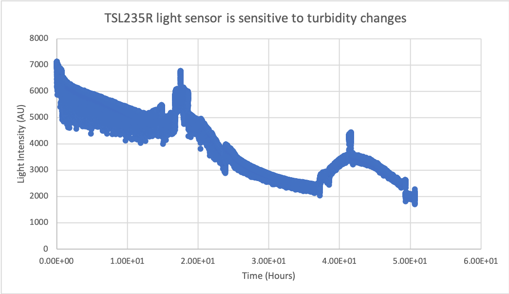
A colony of chloramphenicol-resistant E. coli was picked from a plate and grown in 1 mL of LB media supplemented with 35 µg/mL chloramphenicol. A thin layer of mineral oil was added to the top of the cuvette to prevent evaporation. The cells were grown at room temperature.
Despite these early successes, we decided to focus on efforts on troubleshooting our PREDCEL+ implementation of the T7 to T3 evolution (see “Novel Selection Schema” page). We plan to continue honing our hardware after developing sufficient intuition for working with PREDCEL+.